Contents
Building an SD-WAN network between CPE devices
To transfer traffic, you need to build an SD-WAN network between CPE devices using links that are established on top of the underlay network. CPE devices establish links from all available SD-WAN interfaces of the WAN type. The links are unidirectional. This means that when establishing a link from CPE 1 to CPE 2, a link is automatically established also from CPE 2 to CPE 1. Before building an SD-WAN network, you must ensure connectivity between CPE devices.
Links are established based on the roles that you assign to CPE devices. You can assign the SD-WAN Gateway role or the standard CPE device role to a CPE device. SD-WAN Gateways establish links with all standard CPE devices and other SD-WAN Gateways. Standard CPE devices establish links only with SD-WAN Gateways. By default, all CPE devices have the standard CPE device role.
If you want a link to be established between two standard CPE devices, you need to assign the same topology tag to these standard CPE devices. You can also make a standard CPE device a transit device to allow other CPE devices to establish links through that CPE device.
The links between CPE devices form a topology. The following topologies are the most commonly used in Kaspersky SD-WAN:
- In a Hub-and-Spoke topology, links between CPE devices are established through SD-WAN gateways.
- In Full-Mesh and Partial-Mesh topologies, links between CPE devices are established directly, or some links are established directly, while others are established through SD-WAN gateways.
Within the SD-WAN network, traffic between CPE devices can take multiple paths. The paths go through the links between CPE devices. The totality of all possible paths between two CPE devices is called a segment. The segment source CPE device can distribute the traffic bound to the segment destination CPE device across multiple paths. One segment can contain 2 to 16 paths.
The following path types are supported:
- Auto-SPF (Shortest-Path Forwarding) is a path that is automatically calculated by the controller. You can forward traffic along Auto-SPF paths in two modes:
- In Active/Active mode, multiple Auto-SPF paths are used simultaneously to forward traffic between CPE devices.
- In Active/Standby mode, one Auto-SPF path with the lowest cost is used to forward traffic between CPE devices. If the Auto-SPF path being used becomes unavailable, the Auto-SPF path with the next lowest cost is used. The path cost is calculated by adding up the cost of every link traversed by the path. You can manually specify link cost.
You can configure the traffic forwarding mode along Auto-SPF paths when configuring the paths.
- Auto-TE (Traffic Engineering) is a path automatically calculated by the controller, taking into account the threshold constraints you specified.
- Manual-TE is a path that you manually created. When creating a Manual-TE path, specify the links that the path passes through on the way from the segment source CPE device to the segment destination CPE device.
About the Hub-and-Spoke topology
In a Hub-and-Spoke topology, the hub site is connected to multiple spoke sites to exchange traffic. This topology is the most common for SD-WAN network design because it simplifies network management and provides a higher level of security by routing traffic through the hub site where traffic analysis and categorization is performed. The Hub-and-Spoke topology also enables more efficient use of bandwidth by optimizing and prioritizing traffic at the hub site.
To build a Hub-and-Spoke topology, you need to assign the SD-WAN gateway and standard CPE roles to CPE devices. In this case, SD-WAN gateways establish links with other SD-WAN gateways and standard CPE devices, while standard CPE devices establish links only with SD-WAN gateways.
You can use quality of service to limit bandwidth for CPE devices or traffic classes.
Examples of Hub-and-Spoke topologies:
- Hub-and-Spoke topology without connection between spoke sites.
The figure below shows a Hub-and-Spoke topology in which spoke sites communicate with the hub site, but not with each other. SD-WAN networks built using this topology are easy to design and maintain, because all necessary network services and applications are located in the same data center.
CPE devices being registered are automatically included in the management transport service with the Leaf role and can be behind NAT (Network Address Translation) and PAT (Port Address Translation). In such a Hub-and-Spoke topology, traffic cannot be transmitted directly between CPE devices.
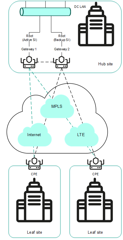
Hub-and-Spoke topology without connection between spoke sites
- Hub-and-Spoke topology with connection between spoke sites through the hub site.
The figure below shows a Hub-and-Spoke topology in which spoke sites can communicate with each other through the hub site. CPE devices being registered are automatically added to the management transport service and may be behind NAT and PAT.

Hub-and-Spoke topology with connection between spoke sites through the hub site
About Full-Mesh and Partial-Mesh topologies
In Full-Mesh and Partial-Mesh topologies, links are established between standard CPE devices. Establishing links between standard CPE devices has the following advantages over a Hub-and-Spoke topology in which standard CPE devices must communicate with each other through SD-WAN gateways:
- Improved aspects of link quality, such as delay, packet loss, and jitter.
- Higher bandwidth of links.
- Economy of hardware resources of SD-WAN gateways.
To build a Full-Mesh topology, you need to assign the standard CPE device role to the CPE devices and assign the same topology tag to the standard CPE devices. In this case, standard CPE devices with the same topology tags establish links with each other.
To build a Partial-Mesh topology, you need to assign the SD-WAN gateway and standard CPE device roles to the CPE devices and assign the same topology tag to the standard CPE devices. In this case, SD-WAN gateways establish links with other SD-WAN gateways and with standard CPE devices, while the standard CPE devices establish links with SD-WAN gateways and with each other provided the same topology tag is assigned to the standard CPE devices. If you want to divide the standard CPE devices into groups, you need to assign a unique topology tag to all standard CPE devices in each group, and also assign a topology tag to be shared by at least one standard CPE device in each group.
You can use quality of service to limit bandwidth for CPE devices or traffic classes.
Full-Mesh and Partial-Mesh topology examples:
- Full-Mesh topology.
The figure below shows a Full-Mesh topology in which all CPE devices establish links with each other. Traffic between CPE 1 and CPE 2 devices is forwarded directly. With a large number of CPE devices and links, this topology can be extremely taxing on the resources of the controller.
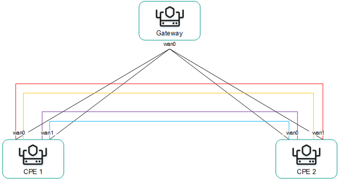
Full-Mesh topology
- Partial-Mesh topology.
The figure below shows a Partial-Mesh topology. This topology is used when direct links between some CPE devices may be undesirable for administrative reasons, or impossible for technical reasons. In this topology, you can group CPE devices in such a way that CPE devices in the same group communicate directly with each other and communicate with CPE devices from other groups through a transit CPE device.
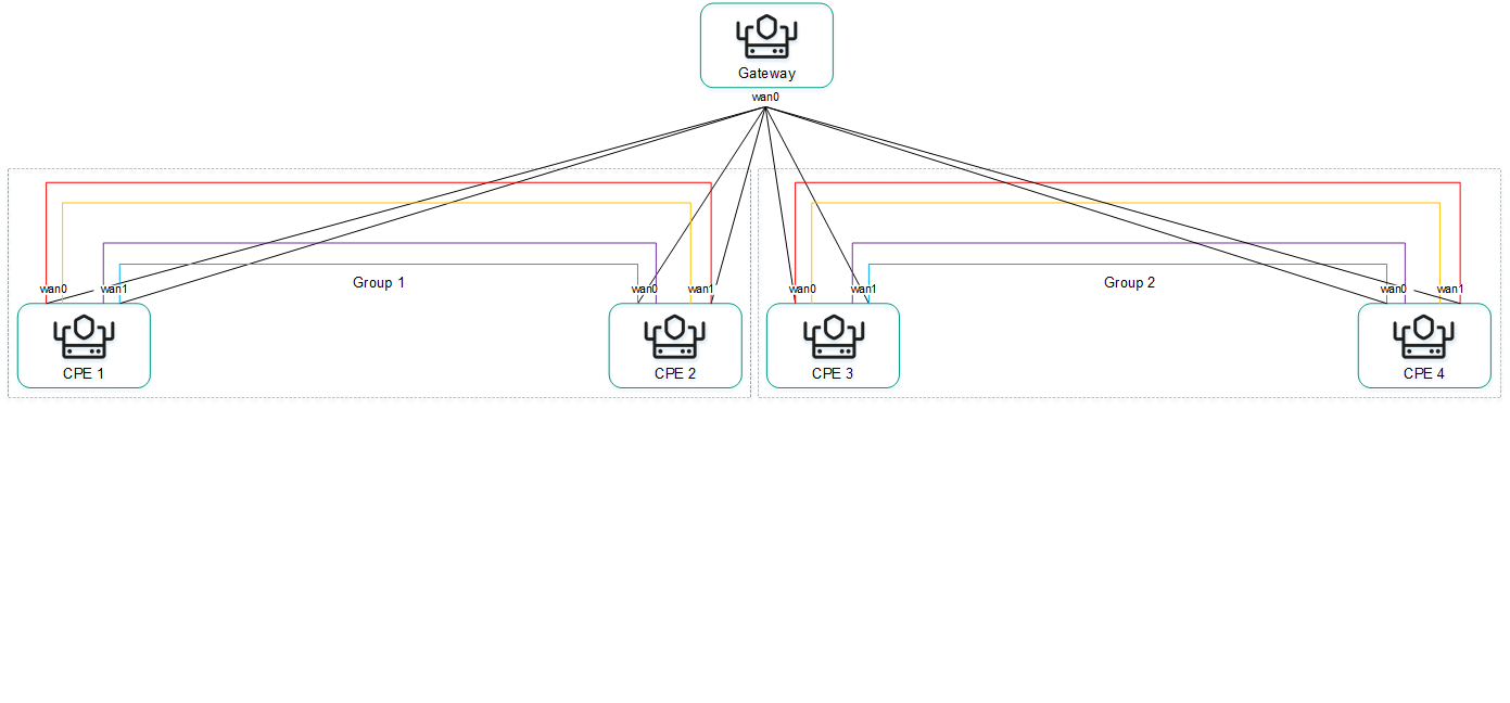
Partial-Mesh topology
A CPE device can belong to multiple groups at the same time, as shown in the figure below.
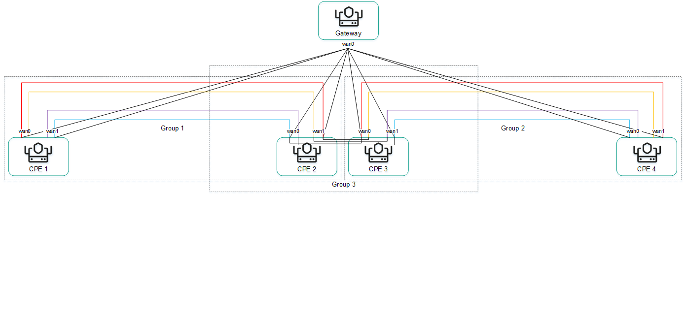
Partial-Mesh topology, CPE devices in multiple groups
When creating direct links between CPE devices, depending on the type of connectivity of the CPE devices through physical links, the following variants of overlay connectivity are possible:
- All physical links have direct IP connectivity to each other.
Thanks to the connectivity within the internet, CPE devices can establish the maximum number of links with each other (see the figure below).
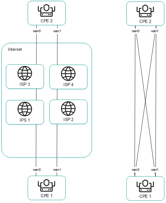
Full physical connectivity between CPE devices
- Physical links have partial IP connectivity to each other.
In the figure below, the internet cloud and the MPLS cloud are not connected to each other, so links can only be established through SD-WAN interfaces of the WAN type that belong to the same cloud. CPE1:WAN0 → CPE2:WAN1 and CPE1:WAN1 → CPE2:WAN0 links cannot be established.
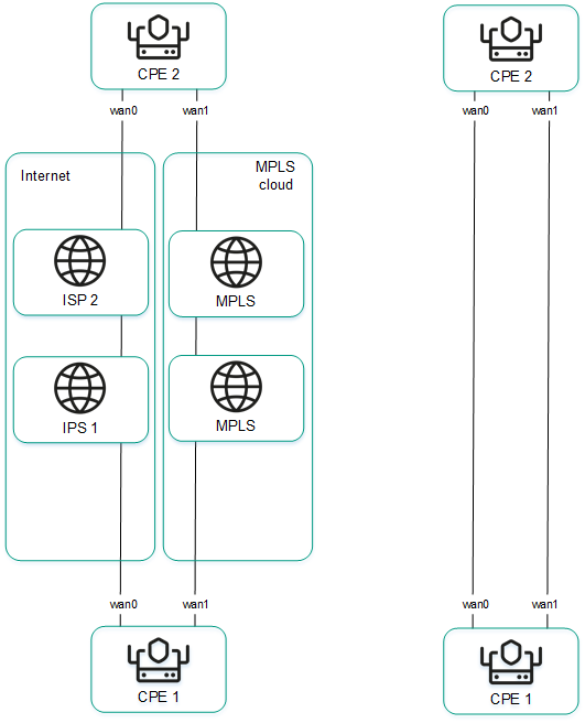
Other overlay network connectivity scenarios are also possible if IP connectivity between SD-WAN interfaces of the WAN type of CPE devices within the same cloud is impossible for other reasons, for example, when using an MPLS topology that does not support direct communication between CPE devices, or due to the presence of NAT/PAT or ACL on the internet.
Assigning a role to a CPE device
You can assign a role to a CPE template or a CPE device. A role assigned to a CPE template is automatically assigned to all CPE devices that use this CPE template.
To assign a role to a CPE device:
- Assign a role to a CPE device in one of the following ways:
- If you want to assign a role to a CPE template, go to the SD-WAN → CPE templates menu section, click the CPE template, and select the Topology tab.
- If you want to assign a role to a CPE device, do one of the following:
- In the menu, go to the SD-WAN → CPE section, click the CPE device, select the Topology tab, and select the Override check box.
- In the menu, go to the Infrastructure section, click Management → Configuration menu next to the controller, go to the Topology tags section, and in the Switch drop-down list, select the CPE device.
- In the Role drop-down list, select the role of the CPE device:
- CPE for a standard CPE device. Default value.
- Gateway for an SD-WAN Gateway. You cannot assign topology tags to SD-WAN gateways.
- Save the CPE device role in one of the following ways:
- If you have assigned a role to a CPE template or a CPE device in the SD-WAN section, in the upper part of the settings area, click Save to save the settings of the CPE template or CPE device.
- If you have assigned a role to a CPE device in the Topology tags section, in the upper part of the page, click Save.
The role is assigned to the CPE device.
Page topAssigning a topology tag to a CPE device
You can assign a topology tag to a CPE template or a CPE device. A topology tag assigned to a CPE template is automatically assigned to all CPE devices that use this CPE template. CPE devices with the same topology tags automatically establish links with each other. A topology tag cannot be assigned to a CPE device if you have assigned the SD-WAN Gateway role to the CPE device.
To assign a topology tag to a CPE device:
- Assign a topology tag to a CPE device in one of the following ways:
- If you want to assign a topology tag to a CPE template, go to the SD-WAN → CPE templates menu section, click the CPE template, and select the Topology tab.
- If you want to assign a topology tag to a CPE device, do one of the following:
- In the menu, go to the SD-WAN → CPE section, click the CPE device, select the Topology tab, and select the Override check box.
- In the menu, go to the Infrastructure section, click Management → Configuration menu next to the controller, go to the Topology tags section, and in the Switch drop-down list, select the CPE device.
Topology tags are displayed.
- In the Topology tags field, enter the topology tag that you want to assign to the CPE device and click the add icon
 .
.The topology tag is assigned to the CPE device. You can assign multiple topology tags or remove a topology tag. To remove a topology tag, click the remove icon
 next to it.
 - Save the topology tags of the CPE device in one of the following ways:
- If you have assigned a topology tag to a CPE template or a CPE device in the SD-WAN section, in the upper part of the settings area, click Save to save the settings of the CPE template or CPE device.
- If you have assigned a topology tag to a CPE device in the Topology tags section, in the upper part of the page, click Save.
Configuring paths
You can configure paths in a segment, CPE template or on the CPE device. Path settings specified in a segment or a CPE template are automatically propagated to all CPE devices that belong to this segment or use this CPE template. Path settings specified on a CPE device are automatically propagated to all CPE devices that belong to the same segment as that CPE device.
To configure paths:
- Configure paths in one of the following ways:
- If you want to configure paths in a segment, go to the Infrastructure section, click Management →Configuration menu next to the controller, go to the Segments section, and click Management → Edit next to the segment.
- If you want to configure paths in a CPE template, go to the SD-WAN → CPE templates menu section, click the CPE template, and select the Multipathing tab.
- If you want to configure paths on a CPE device, go to the SD-WAN → CPE menu section, click the CPE device, and select the Multipathing tab.
Path settings are displayed.
- In the Maximum number of paths field, enter the maximum number of paths supported by the CPE device or segment. Range of values: 1 to 16. Default value:
8. - In the Maximum of Auto-SPF field, enter the maximum number of Auto-SPF paths supported by the CPE device or segment. Auto SPF paths are automatically calculated by the controller. Range of values: 1 to 8. Default value:
2.If you want traffic to be transmitted between CPE devices in Active/Active mode, enter a value greater than
1in this field. If you want traffic to be transmitted between CPE devices in Active/Standby mode, enter1in this field. - In the Cost variance multiplier field, enter the maximum ratio of the cost of this path to the lowest cost of any path on your SD-WAN network; if the cost of the path is below this limit, the path can be added to the segment. Range of values: 1.0 to 10.0. Default value:
10. You cannot enter a value in this field if the Multi-weight balancing check box is selected.For example, if you enter
2in this field, and the lowest path cost in your SD-WAN network is 10,000, paths with a cost of up to 20,000 can be added to the segment. In Active /Standby mode, the value in this field determines which Auto-SPF path is used if the previous Auto-SPF path becomes unavailable. - If you want paths to be added to the segment regardless of their cost, select the Multi-weight balancing check box. This check box is cleared by default.
- Save the path settings in one of the following ways:
- If you have configured paths in the segment, click Save to save the segment settings.
- If you have configured paths in a CPE template or on a CPE device, in the upper part of the settings area, click Save to save the settings of the CPE template or CPE device.
Path settings are saved.
Page topManaging links
You can view the links in one of the following ways:
- To display the table of links established from a CPE device, go to the SD-WAN → CPE menu section, click the CPE device, and select the Links tab.
- To display the table of all links, go to the Infrastructure menu section, click Management → Configuration menu next to the controller, and go to the Links section.
- To display the graphical topology with all links, go to the Infrastructure menu section, click Management → Configuration menu next to the controller, and go to the Topology section.
When viewing the table of links, information about the links is displayed in the following table columns:
- Source is the name, DPID, and OpenFlow port number of the CPE device that is the link source.
- Destination is the name, DPID, and OpenFlow port number of the CPE device that is the link destination.
- Unsolicited indicates whether the controller uses this link as the last resort when calculating the path, regardless of the monitoring indicators:
- Y
- N
- Thresholds monitoring indicates whether link monitoring is on:
- Y
- N
- MTU is the MTU value of the link.
- Errors/second is the number of errors per second on the link.
- Utilization (%) is the load of the link as a percentage of the bandwidth of the source service interface.
- Latency (ms.) is the delay time in milliseconds for traffic transmitted through the link.
- Jitter (ms.) is the jitter time in milliseconds for traffic transmitted through the link.
- Packet loss (%) is the percentage of traffic packet loss on the link.
- Speed (Mbit/sec.) is the speed of traffic transmission through the link in Mbps.
- Cost is the link cost.
The actions you can perform with the table are described in the Managing solution component tables instructions.
Specifying the cost of a link
To specify the cost of a link:
- Specify the link cost in one of the following ways:
- If you want to specify the cost of a link that was established from a CPE device, go to the SD-WAN → CPE section, click the CPE device, select the Links tab, and click Management → Set cost next to the link.
- If you want to specify the cost of one of the links in the table of all links, go to the Infrastructure section, click Management → Configuration menu next to the controller, go to the Links section, and click Management → Set cost next to the link.
- If you want to specify the cost of one of the links in the graphic topology with all links, go to the Infrastructure section, click Management → Configuration menu next to the controller, go to the Topology section, click the link, and click Set cost.
- This opens a window; in that window, select the Override check box to specify the cost of the link. This check box is cleared by default.
- In the Tunnel cost field, enter the cost of the link. If you want to specify the same cost for the opposite-direction link, select the Save for both tunnels check box. This check box is cleared by default.
- Click Save.
The link cost is specified.
- If you have specified the link cost for a link established from the CPE device, click Save in the upper part of the settings area to save the CPE device settings.
Enabling Dampening
Dampening is a configurable mechanism that excludes unstable links whose state changes too frequently from path calculation. When determining link instability, the following state changes are taken into account:
- UP/LIVE → DOWN/NOT-LIVE.
- DOWN/NOT-LIVE → UP/LIVE.
- UP/LIVE → UP/NOT-LIVE.
- UP/NOT-LIVE → UP/LIVE.
When Dampening is enabled, each state change of the link increases the Penalty value. If the Penalty reaches the threshold within the specified time, access to the link is restricted (its cost is increased 10,000 times for the specified period of time). The value of each of these parameters is specified when you enable Dampening. By default, access to the link is resumed if the state of the link does not change for 10 minutes.
To enable Dampening:
- Enable Dampening in one of the following ways:
- If you want to enable Dampening for a link that was established from a CPE device, go to the SD-WAN → CPE section, click the CPE device, select the Links tab, and click Management → Dampening next to the link.
- If you want to enable Dampening for one of the links in the table of all links, go to the Infrastructure section, click Management → Configuration menu next to the controller, go to the Links section, and click Management → Dampening next to the link.
- If you want to enable Dampening for one of the links in the graphic topology with all links, go to the Infrastructure section, click Management → Configuration menu next to the controller, go to the Topology section, click the link, and click Dampening.
- This opens a window; in that window, select the Enable check box to enable Dampening on the link. This check box is cleared by default.
- In the Maximum suppress time (ms.) field, enter the time, in milliseconds, for which access to the link can be restricted. When the specified time elapses, all Dampening counters on the link are reset. Default value:
600000. - In the Penalty field, enter the number by which Penalty is incremented when the link changes state. Default value:
1. - In the Suppress threshold field, enter the Penalty value at which access to the link is restricted. Default value:
4. - In the Update interval (ms.) field, enter the time in milliseconds during which Penalty must attain the value specified in the Suppress threshold field for access to the link to be restricted. Default value:
120000. - If you want to view Dampening statistics for a link, click Load statistics.
- Click Save.
Dampening is enabled for the link.
- If you enabled Dampening for a link established from the CPE device, click Save in the upper part of the settings area to save the CPE device settings.
Enabling Forward Error Correction
The Forward Error Correction (FEC) functionality reduces the loss of traffic packets in links, especially for UDP applications, and the number of retransmissions, which lead to delays, and also recovers received data on the CPE device. Data recovery is provided by redundant encoding of the data stream on the device on the source CPE device.
The source CPE device encodes the traffic packet stream transmitted through the link and adds redundant traffic packets. Encoding on CPE devices may cause delays due to extra data processing.
The destination CPE device buffers traffic packets received through the link and decodes them, recovering lost traffic packets, if possible. We recommend using FEC on noisy links to reduce the packet loss and increase the speed of TCP connections. The general diagram of FEC is shown in the figure below.
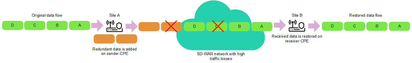
FEC diagram
To enable FEC:
- Enable FEC in one of the following ways:
- If you want to enable FEC for a link that was established from a CPE device, go to the SD-WAN → CPE section, click the CPE device, select the Links tab, and click Management → FEC/reordering next to the link.
- If you want to enable FEC for one of the links in the table of all links, go to the Infrastructure section, click Management → Configuration menu next to the controller, go to the Links section, and click Management → FEC/reordering next to the link.
- If you want to enable FEC for one of the links in the graphic topology with all links, go to the Infrastructure section, click Management → Configuration menu next to the controller, go to the Topology section, click the link, and click FEC/reordering.
- This opens a window; in that window, select the Override check box to enable FEC on the link. This check box is cleared by default.
- In the Redundancy ratio (original/redundant packet) drop-down list, select the ratio of original traffic packets to extra traffic packets with redundant code. Default value: 0:0 FEC off means FEC is not used. You can also specify the ratio of original traffic packets to redundant traffic packets by using the
topology.link.fec.ratiocontroller property. - In the Timeout field, enter the time, in milliseconds, during which a traffic packet can stay in the queue for FEC to apply. Range of values: 1 to 1000.
- Click Save.
FEC is enabled.
- If you enabled FEC for a link established from the CPE device, click Save in the upper part of the settings area to save the CPE device settings.
Determining the MTU value
You can determine the MTU value of a link to find out why fragmented packets are being blocked on the link (see the figure below).
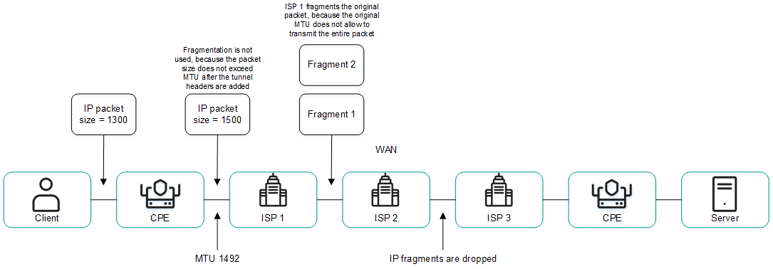
Links with a reduced MTU size and fragmented packet getting dropped
The MTU value is determined by sending LLDP packets with a variable payload size through the link. The minimum detectable MTU size is 1280 bytes, and the maximum is 1500 bytes. The MTU value is determined automatically when CPE devices are enabled and periodically at an interval specified in the topology.link.pmtud.scheduler.interval.sec controller property.
You can determine the MTU value manually.
To manually determine the MTU value,
Determine the MTU value in one of the following ways:
- If you want to manually determine the MTU value for a link that was established from a CPE device, go to the SD-WAN → CPE section, click the CPE device, select the Links tab, and click Management → Check MTU next to the link.
- If you want to manually determine the MTU value for one of the links in the table of all links, go to the Infrastructure section, click Management → Configuration menu next to the controller, go to the Links section, and click Management → Check MTU next to the link.
The MTU value is displayed in the MTU column.
Page topTraffic encryption
Traffic encryption is a mechanism of securing the exchange of traffic between CPE devices through links. For example, you can encrypt traffic that is transmitted over unsecured connections.
Traffic encryption does not replace the need to use other information security measures, such as TLS, LDAPS, and other protocols that protect traffic within the overlay network.
The controller automatically generates keys for encrypting and decrypting traffic and sends the keys to CPE devices. Traffic is encrypted on the source CPE device using the encryption key. The destination CPE device decrypts the traffic using the decryption key.
The keys are regularly updated to deprive third parties of the opportunity to encrypt or decrypt the transmitted traffic if a key is intercepted. You can specify the length of time after which the keys are updated on CPE devices using the topology.link.encryption.key.update.interval.minutes controller property.
Traffic encryption is supported only on CPE devices running Kaspersky SD-WAN software.
If traffic encryption is enabled on a CPE device, all outbound links that involve this CPE device send encrypted traffic (including new links that will be established later). If traffic encryption is disabled on a CPE device, it sends unencrypted traffic. If you disable traffic encryption on a CPE device that had been encrypting its outgoing traffic, the keys generated by the SD-WAN Controller for encrypting and decrypting traffic are deleted from all related CPE devices.
You can also enable or disable traffic encryption on links. For example, you can enable traffic encryption on a CPE device, but disable it on a link built with the participation of this CPE device. When enabling or disabling traffic encryption on a link, you need to configure the opposite-direction link in the same way.
Enabling traffic encryption on a CPE device
You can enable or disable traffic encryption in a CPE template or on a CPE device. Traffic encryption settings specified in the CPE template are automatically propagated to all CPE devices that use this CPE template.
To enable traffic encryption on a CPE device:
- Enable traffic encryption on the CPE device in one of the following ways:
- If you want to enable traffic encryption in a CPE template, go to the SD-WAN → CPE templates menu section, click the CPE template, and select the Tunnel encryption tab.
- If you want to enable traffic encryption on a CPE device, go to the SD-WAN → CPE menu section, click the CPE device, select the Tunnel encryption tab, and select the Override check box.
The traffic encryption policy is displayed.
- In the Default encryption policy drop-down list, select one of the following values:
- Enabled
- Disabled Default value.
- In the upper part of the settings area, click Save to save the settings of the CPE template or CPE device.
Enabling traffic encryption on a link
When enabling or disabling traffic encryption on a link, you must configure the opposite-direction link in the same way.
To enable encryption of traffic on a link:
- Enable traffic encryption on the link in one of the following ways:
- If you want to enable traffic encryption for a link that was established from a CPE device, go to the SD-WAN → CPE section, click the CPE device, select the Links tab, and click Management → Set encryption next to the link.
- If you want to enable traffic encryption for one of the links in the table of all links, go to the Infrastructure section, click Management → Configuration menu next to the controller, go to the Links section, and click Management → Set encryption next to the link.
- If you want to enable traffic encryption for one of the links in the graphic topology with all links, go to the Infrastructure section, click Management → Configuration menu next to the controller, go to the Topology section, click the link, and click Set encryption.
- This opens a window, in that window, select the Override check box. This check box is cleared by default.
- Select the Enable encryption check box to enable traffic encryption for the link. This check box is cleared by default.
- Click Save.
Traffic encryption is enabled on the link.
- If you enabled traffic encryption for a link established from the CPE device, click Save in the upper part of the settings area to save the CPE device settings.
Managing segments
To display the table of segments, go to the Infrastructure menu section, click Management → Configuration menu next to the controller, and go to the Segments section. Information about segments is displayed in the following columns of the table:
- From is the name and DPID of the CPE device of the segment source.
- To is the name and DPID of the CPE device of the segment destination.
- Paths/maximum is the number of paths created and the maximum number of paths supported by the segment.
- # is the sequential number of the path. The lower the path number, the earlier the path was built.
- Path type is the type of the path:
- Auto SPF
- Auto TE
- Manual TE
- Transport paths are names, DPIDs, and numbers of OpenFlow ports of CPE devices through which the path passes.
- Administrative state is the administrative state of the path:
- up
- down
- Operational state is the operational state of the path:
- up
- down
- Cost is the the cost of the path.
- Hop count is the number of hops in the path.
The actions that you can perform with the table are described in the Managing solution component tables instructions.
When creating or editing a Manual-TE path in a segment, you can view the table of hops added to the Manual-TE path. Information about hops is displayed in the following columns of the table:
- # is the sequential number of the hop. The lower the number of the hop, the earlier the hop was added.
- From is the name, DPID, and OpenFlow port number of the CPE device that is the hop source.
- To is the name, DPID, and OpenFlow port number of the CPE device that is the hop destination.
- Cost is the the cost of the hop.
The total cost of the Manual-TE path is displayed in the lower part of the table.
Page topCreating a Manual-TE path
When creating a Manual-TE path, you must manually specify the links that the path passes through on the way from the segment source CPE device to the segment destination CPE device. Two types of Manual-TE paths are supported:
- A fully defined Manual-TE path specifies each CPE device and service interface through which the Manual-TE path passes.
- A hybrid Manual-TE path specifies one or more CPE devices and service interfaces through which the Manual-TE path passes. In this case, traffic between sections of the Manual-TE path that are not manually specified is transmitted automatically (an Auto-SPF path is used).
You can use Manual-TE constraints to add Manual-TE paths to transport services.
Examples of possible Manual-TE paths: In the examples, an OpenFlow port number is specified after the CPE device number, separated by a colon. Fully defined Manual-TE path: CPE 1:3 → CPE 2:1, CPE 2:2 → CPE 4:1, CPE 4:5 → CPE N:2. Hybrid Manual-TE path: CPE 1 → CPE 5, CPE 5:3 → CPE 4:3, CPE 4 → CPE N. In this case, the path from CPE 1 to CPE N is built as an Auto-SPF path CPE 1 → CPE 5, a Manual-TE path CPE 5:3 → CPE 4:3, and an Auto-SPF path CPE 4 → CPE N. |
To create a Manual-TE path:
- In the menu, go to the Infrastructure section.
This opens the resource management page. By default, the Network resources tab is selected, which displays the table of controllers.
- Click Management → Configuration menu next to the controller.
This opens the controller configuration menu. By default, you are taken to the Controller nodes section, which displays a table of controller nodes.
- Go to the Segments section.
A table of segments is displayed.
- Click Management → Edit next to the segment in which you want to create a Manual-TE path.
The settings and the path table are displayed.
- Click + Manual-TE path.
The Manual-TE path settings and the hop table are displayed.
- In the Name field, enter the name of the Manual-TE path.
- In the Maximum number of hops field, enter the maximum number of hops in the Manual-TE path. Range of values: 1 to 8. Default value:
4. - Add the hop to the Manual-TE path:
- In the From drop-down list on the left, select the source CPE device for the hop.
If you are adding the first hop to the Manual-TE path, you can select only the CPE device of the segment source as the source CPE device of the hop. If you have added at least one hop to the Manual-TE path, you can only select the destination CPE device of the previous hop as the source CPE device of the current hop.
- If necessary, in the Port drop-down list on the left, select the OpenFlow port of the hop source. Default value: Automatically means the OpenFlow port is determined automatically.
- In the To drop-down list on the right, select the CPE device at the end of the hop.
If in the Port drop-down list you selected Automatically as the hop source CPE device, you can select any CPE device that is not being used in other hops as the hop destination. In this case, in the Port drop-down list, Automatically is selected for the hop destination CPE device, and the OpenFlow port is detected automatically. Thus, the hop uses an Auto-SPF path.
If in the Port drop-down list, you selected an OpenFlow port for the hop source CPE device, for the hop destination CPE device, you can only use a CPE device that has a link built from that OpenFlow port. In this case, in the Port drop-down list, the OpenFlow port to which the link is built is automatically selected as the hop destination CPE device. Thus, the hop uses the link specified between the two CPE devices.
- If necessary, in the Port drop-down list on the right, select the OpenFlow port of the hop destination CPE device. Default value: Automatically means the OpenFlow port is determined automatically.
- Click Add.
The hop is created and displayed in the table. You can add multiple hops or delete a hop. To delete a hop click Delete next to it.
- In the From drop-down list on the left, select the source CPE device for the hop.
- Click Create.
A check is performed to make sure the destination CPE device of the last hop matches the destination CPE device of the segment in which you are creating the Manual-TE path. If the check is successful, the Manual-TE path is created and displayed in the table, and the column Cost displays the cost of the Manual-TE path, which is the sum total of the cost of all hops that you added to this Manual-TE path.
- Click Save to save the settings of the segment.
Editing a Manual-TE path
To edit a Manual-TE path:
- In the menu, go to the Infrastructure section.
This opens the resource management page. By default, the Network resources tab is selected, which displays the table of controllers.
- Click Management → Configuration menu next to the controller.
- Go to the Segments section.
A table of segments is displayed.
- Click Management → Edit next to the segment in which you want to edit a Manual-TE path.
The settings and the path table are displayed.
- Click Edit next to the Manual-TE path that you want to edit.
- If necessary, edit the Manual-TE path settings. For a description of the settings, see the instructions for creating a Manual-TE path.
- Click Save.
The Manual-TE path is modified and updated in the table.
- Click Save to save the settings of the segment.
Deleting a Manual-TE path
Deleted Manual-TE paths cannot be restored.
To delete a Manual-TE path:
- In the menu, go to the Infrastructure section.
This opens the resource management page. By default, the Network resources tab is selected, which displays the table of controllers.
- Click Management → Configuration menu next to the controller.
- Go to the Segments section.
A table of segments is displayed.
- Click Management → Edit next to the segment in which you want to delete a Manual-TE path.
The settings and the path table are displayed.
- Click Delete next to the Manual-TE path that you want to delete.
- Click Save to save the settings of the segment.